
Overview
This guide explains how to install and configure a Synaccess leak detection and automatic water shutoff system. It is written for someone who has not used a PDU or these accessories before.
The SynLink PDU is the system controller. It continuously reads each leak sensor through a Smart Hub, sends email alerts when configured, and shuts off the mapped water valve or valves when a leak remains present for the configured trigger delay. A valve stays off until a person has corrected the problem and intentionally restores the water supply.
Typical applications include laboratories, test benches, cooling-water loops, equipment rooms, and other installations where an unexpected leak could damage equipment or interrupt operations.
This guide is specifically for the SPA-0150 Smart Hub shown in the supplied photographs. The PDU GUI may identify it generically as SynLink Smart Hub, Smart IO Hub, or IO Hub.
System capacity and topology
One Smart Hub supports:
- Six leak sensor inputs, numbered Digital Input 1–6.
- Six valve controls, numbered Power Output/Output Relay 1–6.
A compatible SynLink PDU has two sensor ports, A and B. It can therefore support up to two hubs, for a maximum of 12 leak sensors and 12 valve controls.
SynLink PDU control module
|
+-- Sensor Port A --> Smart Hub A
|                    +-- Digital Inputs 1-6 --> up to 6 leak detectors
|                    +-- Power Outputs 1-6  --> up to 6 water valves
|
+-- Sensor Port B --> Smart Hub B
                     +-- Digital Inputs 1-6 --> up to 6 leak detectors
                     +-- Power Outputs 1-6  --> up to 6 water valves
The Leak Detection setup wizard configures one hub at a time. Mappings created in the wizard stay within the selected hub: sensors on hub A map to valves on hub A, and sensors on hub B map to valves on hub B.
Before you begin
Safety requirements
Important: The automated shutoff system reduces leak damage; it is not a substitute for proper plumbing design, pressure relief, drainage, inspection, or an approved life-safety system.
- Have a qualified plumber install the valve. Isolate and depressurize the line before cutting or opening it.
- Confirm that every valve is rated for the liquid, temperature, pressure, pipe size, flow direction, and surrounding environment.
- Keep the Smart Hub, PDU, power supply, connectors, and leak-detector interface module dry. Only the sensing rope belongs in the monitored leak area.
- Secure cables and sensing rope so they cannot be crushed, cut, pulled, or create a trip hazard.
- Do not restore water automatically after a leak. An authorized person must inspect the area, correct the cause, confirm the sensor is dry, and reopen the supply deliberately.
- Test the completed installation under controlled conditions before relying on it.
Items required
- Compatible SynLink SP Series PDU with network access and available sensor port A or B.
- SPA-0150 Smart Hub with its DT-connector harness, power supply, and supplied PDU-to-hub interface cable.
- One compatible leak-detector interface module and sensing rope per monitored zone.
- One compatible two-wire automatic-return solenoid or ball valve per controlled supply.
- Computer on a network that can reach the PDU web interface.
- PDU account with permission to view sensors, modify event automation, and configure network/SMTP settings.
- SMTP server name, port, TLS requirement, username, password or app password, and one or two alert recipient addresses.
- Labels for both ends of every sensor and valve cable.
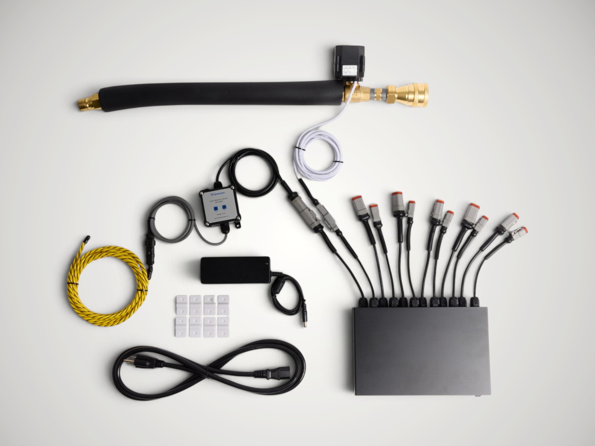
Figure 1 — Example system components. The SynLink PDU itself is not pictured.
Create a port plan
Record the physical connections before installation. Use location names that another person can understand during an emergency.
| Hub port | Channel | Leak sensor location | Valve location | Valve(s) to shut off |
|---|---|---|---|---|
| A | 1 | North lab bench cold-water loop | Main cold-water supply | A-1 |
| A | 2 | Chiller return manifold | Main cold-water supply | A-1 |
| A | 3 | Test stand 3 floor tray | Test stand 3 supply and return | A-3, A-4 |
Label channels as A-S1, A-V1, B-S1, and so on. The hub port letter is important when two hubs are installed.
Part 1 — Hardware setup
1. Identify the SPA-0150 Smart Hub connections
The Smart Hub front panel contains:
- Input Power — connection for the supplied hub power adapter.
- SynLink Interface — connection to PDU sensor port A or B using the supplied interface cable.
- Input Power, Main Power Active, and Status indicators.
- Six Power Outputs indicators and six Sensors indicators.
- Power Output ON/OFF switch. The GUI calls this the User Switch.
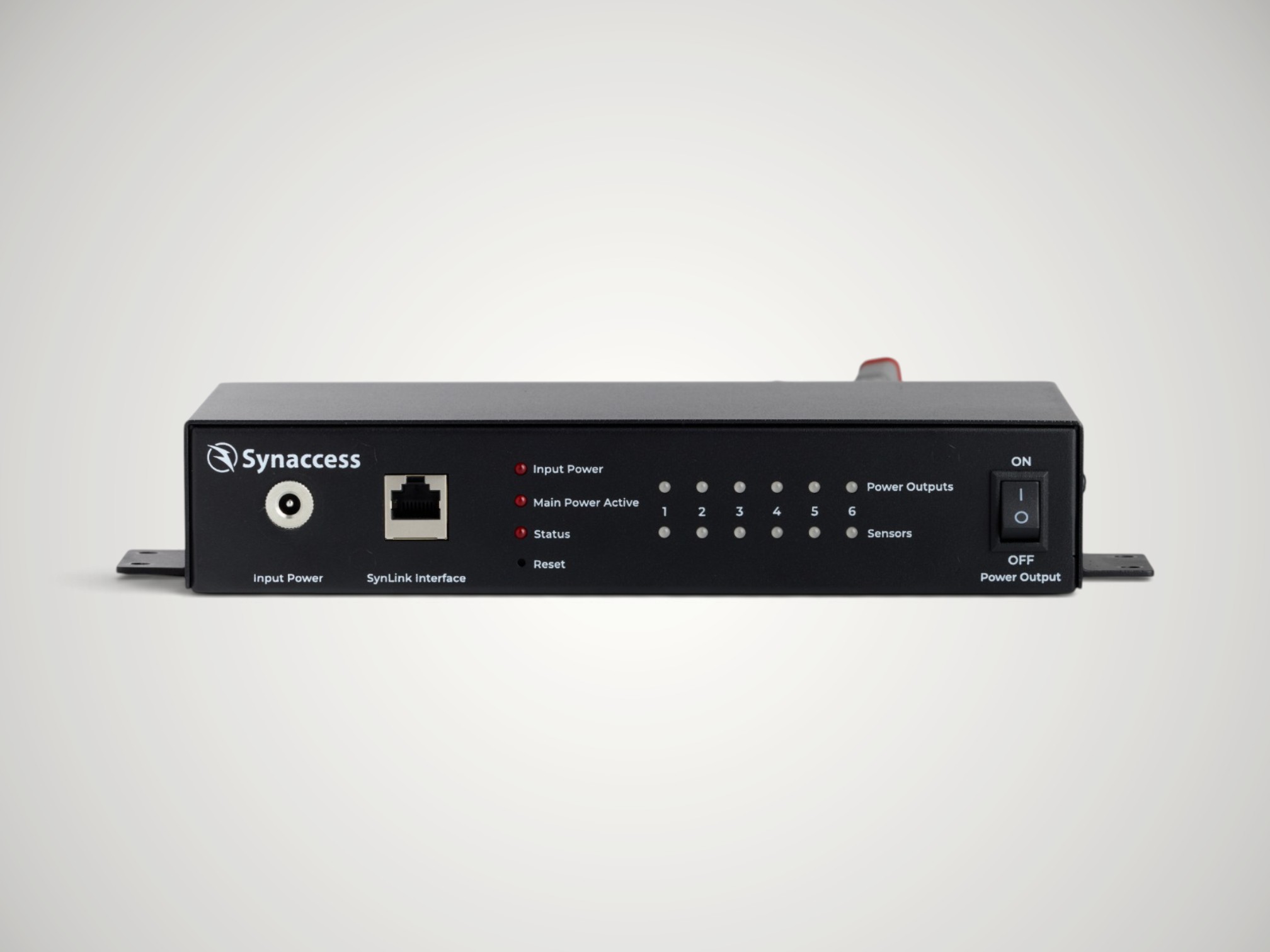
Figure 2 — Smart Hub front panel.
The SPA-0150 rear cable set provides six numbered sensor connections and six numbered valve power/output connections using the sealed DT connectors pictured below. Match each DT connector to the intended accessory connector. Do not force a connector or use a channel only because it is physically nearby; verify its number against the panel label and your port plan.
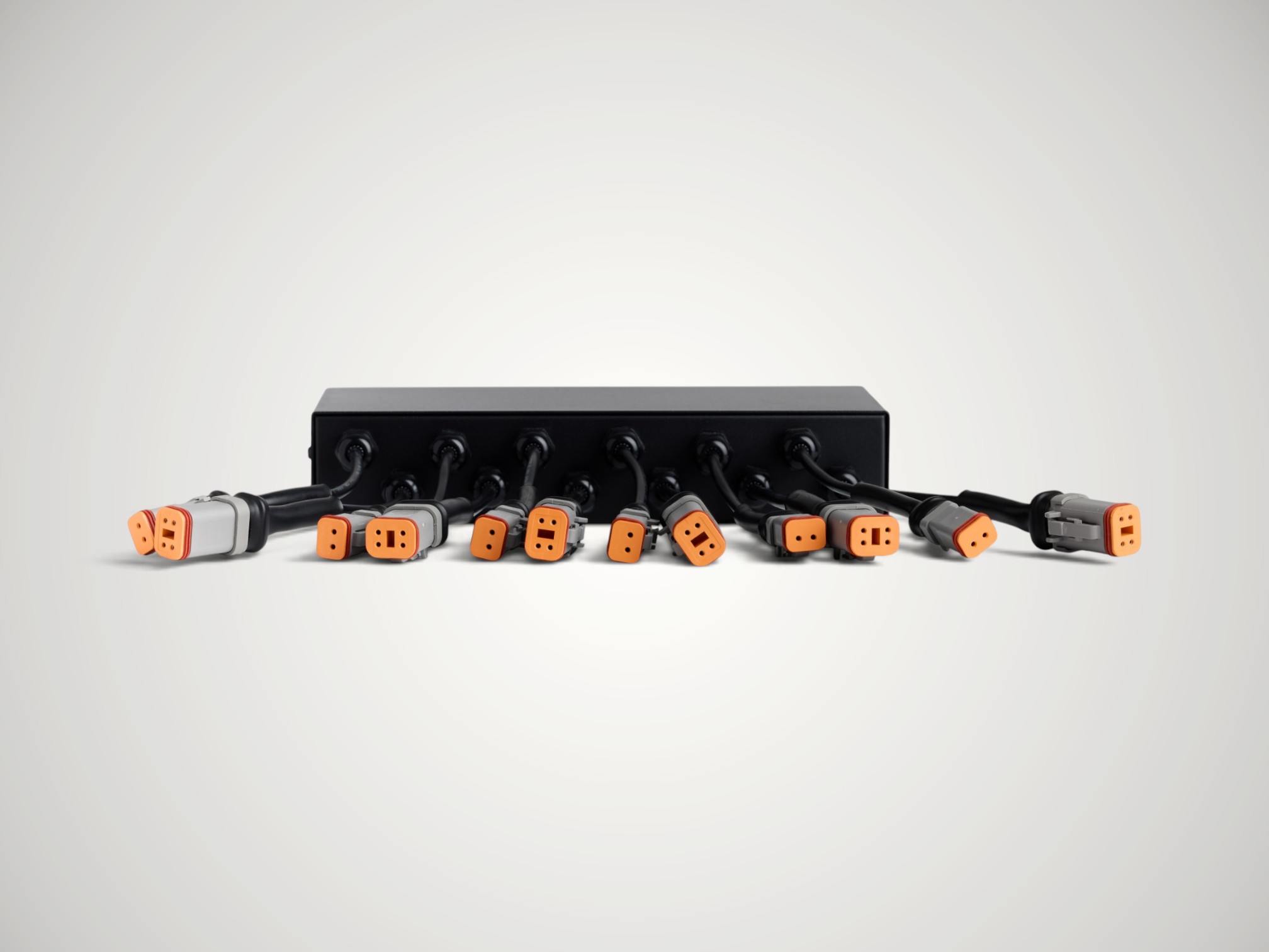
Figure 3 — SPA-0150 DT sensor and valve connections.
2. Install the water valve
- Turn off, isolate, and depressurize the water supply.
- Have a qualified installer fit the valve in the correct flow direction.
- Support the pipe and valve so the actuator and cable do not carry pipe weight.
- Keep the actuator and electrical lead away from standing water and hot surfaces.
- Leave the supply isolated until all wiring and initial checks are complete.
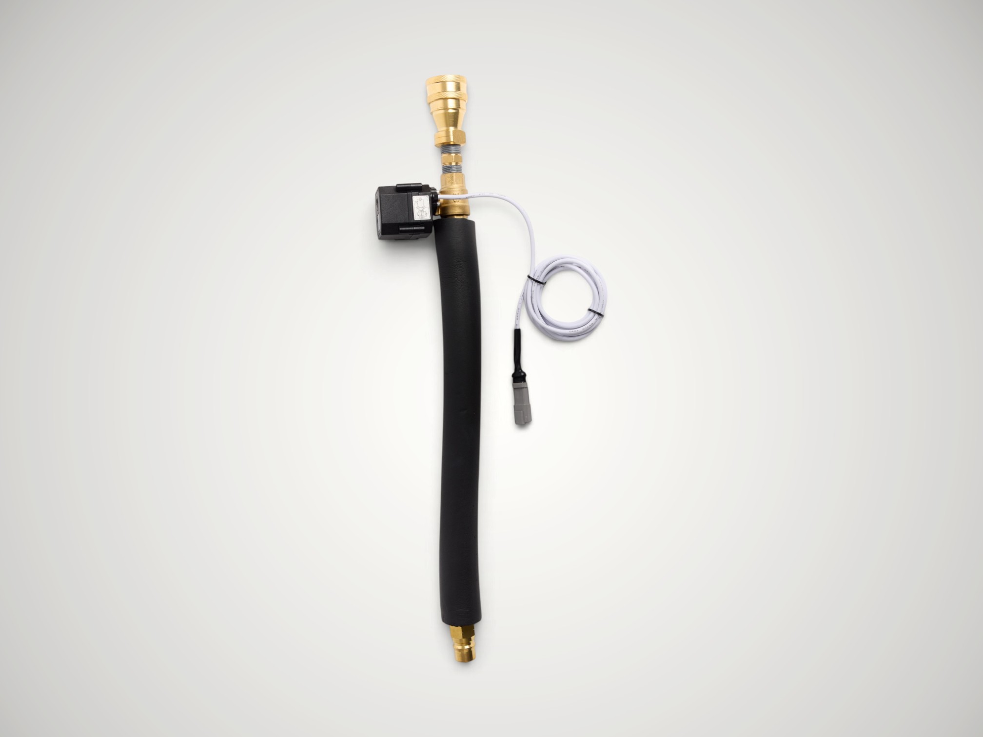
Figure 4 — Example automatic-return water valve assembly.
3. Place the leak sensing rope
- Place the sensing rope along the lowest likely leak path: beneath fittings, hose connections, pumps, heat exchangers, manifolds, or drip trays.
- Use the supplied clips to keep the rope in position. Do not overlap it, sharply kink it, compress it under equipment, or place it where normal condensation will create nuisance alarms.
- Keep the end connector and the leak-detector interface module out of the wet zone.
- Connect the sensing rope to the leak-detector interface module.
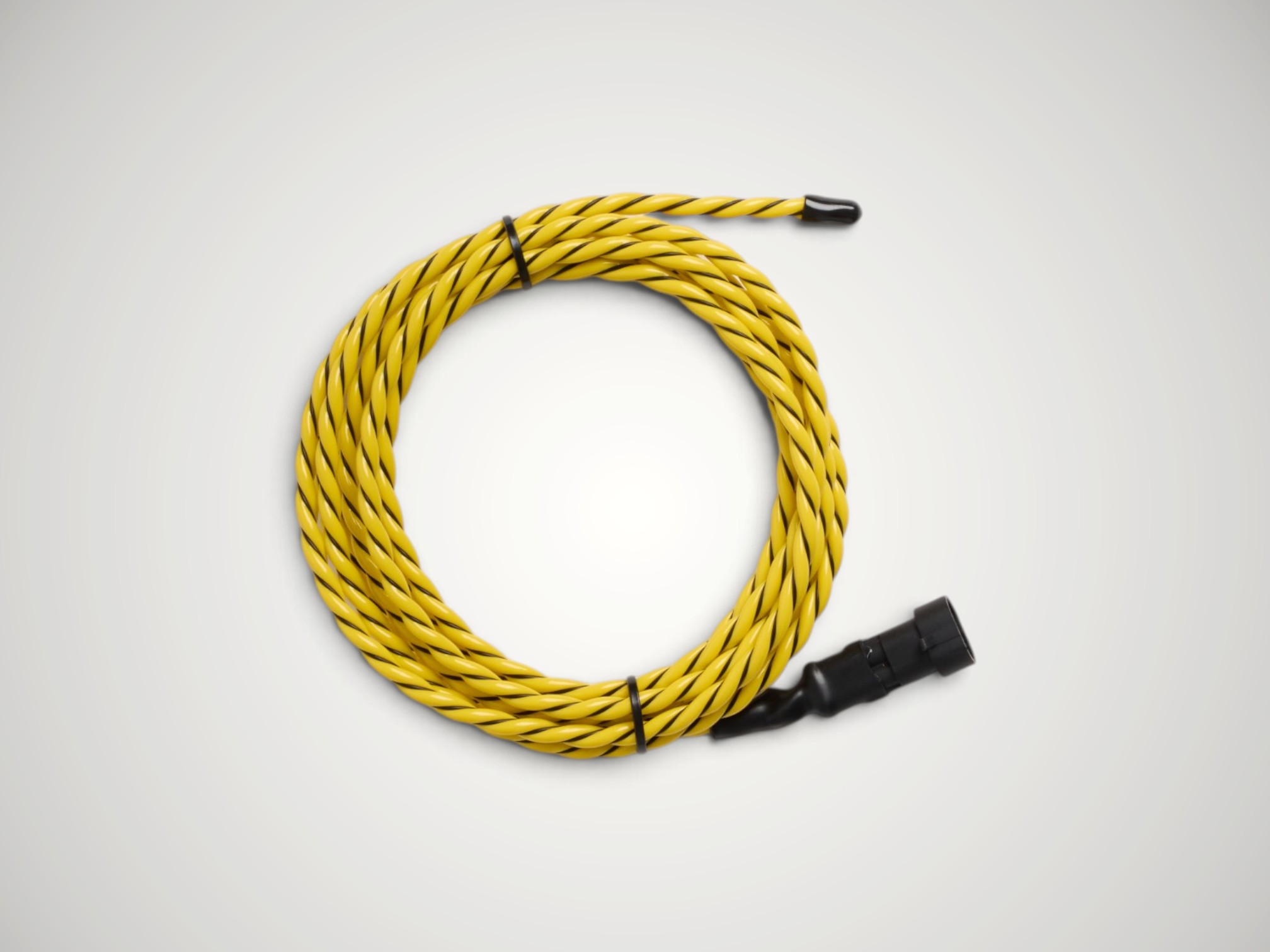
Figure 5 — Rope-style leak sensor.
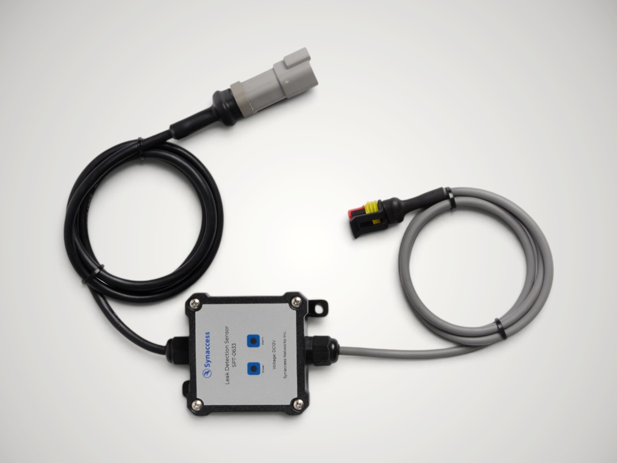
Figure 6 — Leak-detector interface module. The supplied photo is labeled SPT-0683.
4. Connect sensors and valves to the Smart Hub
- Set the Smart Hub Power Output switch to OFF so a valve cannot move unexpectedly while it is being connected.
- Connect each leak-detector interface lead to its planned Digital Input 1–6.
- Connect each valve lead to its planned Power Output/Output Relay 1–6.
- Label both ends of every cable with its hub letter and channel number.
- Check every physical connection against the port plan. A correct software name cannot compensate for a cable connected to the wrong channel.
5. Connect the Smart Hub to the PDU
- Connect the supplied power adapter to the Smart Hub Input Power connector and then to an approved power source.
- Connect the supplied interface cable from the hub SynLink Interface to Sensor Port A or Sensor Port B on the PDU.
The SynLink interface uses an Ethernet-style cable, but this connection is between the Smart Hub and a PDU sensor port. Do not connect the hub to a network switch or to the PDU's network/LAN port.
- Turn on the hub and confirm the Input Power, Main Power Active, and Status indicators show normal operation.
- Keep the front Power Output switch OFF until the valve installation is ready for a controlled movement test.
- If using a second hub, repeat these steps with the other PDU sensor port.
Part 2 — Initial PDU access and hardware verification
1. Log in to the PDU
- Obtain the PDU IP address from the PDU display or your network administrator.
- From a computer that can reach the PDU, open
http://<PDU-IP>orhttps://<PDU-IP>as configured for your site. - Sign in with the credentials supplied by your administrator. Change factory-default credentials before placing the system in service.
2. Confirm that the hub and channels are visible
- Open System > Sensors.
- Confirm that SynLink Smart Hub appears on the expected port, A or B.
- Open the hub details and verify that six digital inputs and six output relays are listed.
- Compare the displayed channel states with the physical labels.
If the hub is not shown, stop here and correct power or interface-cable problems before creating automation.
3. Prove sensor polarity before saving automation
This step is required because the PDU must know whether HIGH or LOW represents water.
- Keep the sensing rope clean and completely dry. Record the digital input state shown by the PDU.
- Apply a small amount of clean tap water across a short section of rope. Do not wet the interface module or connectors.
- Refresh the sensor page and record the wet state.
- Dry the rope completely and confirm it returns to its original state.
For the supplied detector, the expected result is normally:
| Rope condition | Digital input state |
|---|---|
| Dry | LOW |
| Wet | HIGH |
If your observed states are reversed, use the observed wet state in the software wizard. Never choose a state from this table without performing the test.
4. Prove each valve's physical operation
- Make sure the plumbing test can be performed safely and that a manual upstream isolation is available.
- Move the hub Power Output switch to ON.
- From the hub sensor page or Leak Detection status page, operate one output at a time.
- Confirm that ON allows flow and OFF closes the intended physical valve.
- Verify that the channel number and location match the port plan.
- Return every channel to its intended safe commissioning state.
Relay and valve terminology: The PDU uses
OPENfor the de-energized output-relay command that closes the automatic-return water valve. In customer terms, this is WATER OFF / VALVE CLOSED. Use the GUI's WATER ON/WATER OFF and Operation ON/OFF indicators, then verify the actual valve and water flow.
Part 3 — Configure email notifications
Configure and test SMTP before creating leak alerts.
- Open Settings > SMTP.
- Enter the SMTP server hostname or IP address and port supplied by your email administrator.
- Enable TLS when supported. It is strongly recommended.
- Enable SMTP Authentication Required when required, then enter the account username and password or app password.
- Select Save.
- Under Test SMTP Settings, enter a recipient address and select Send Test Email.
- Confirm the message arrives. Also check spam filtering and mail-gateway logs if it does not.
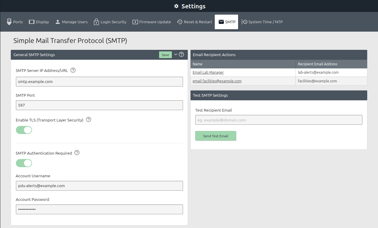
Figure 7 — Completed SMTP page. All addresses and credentials shown in this screenshot are sanitized examples.
Checkpoint: Your SMTP server, port, TLS, authentication, and account fields should be complete before you continue. The values will be different from Figure 7 because they must come from your email administrator. Do not continue until Send Test Email succeeds and the test message arrives.
Email is a secondary notification path. Valve shutoff automation runs locally on the PDU and must not depend on an email being delivered. Network, DNS, SMTP, credential, or mail-provider failures can still prevent notifications.
Part 4 — Create leak detection automation
1. Open the guided setup
- Open Automation > Use Cases.
- Find Leak Detection and Water Shutoff for Smart IO Hub Accessory.
- Select View Use Case.
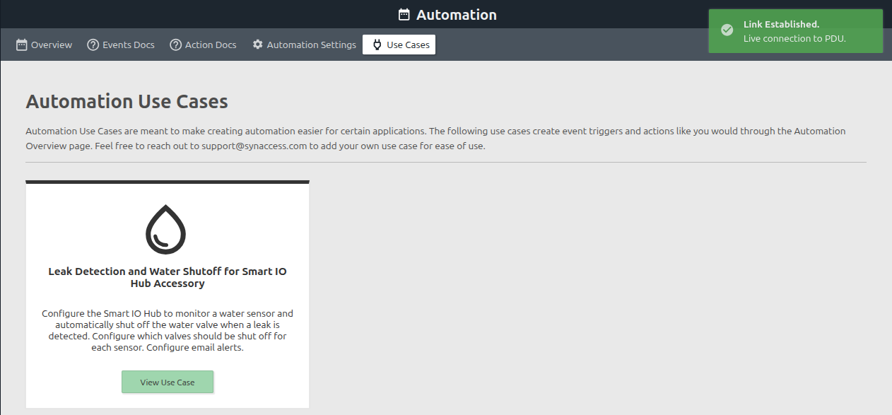
Figure 8 — Automation > Use Cases before leak automation has been created.
Checkpoint: You should see the water-drop icon, the leak detection description, and the View Use Case button shown in Figure 8.
2. Select the connected SPA-0150
- In IO Hub Status, find the connected hub on port A or B.
- Confirm Connectivity is Connected.
- For a new installation, confirm the button says Set Up and select it.
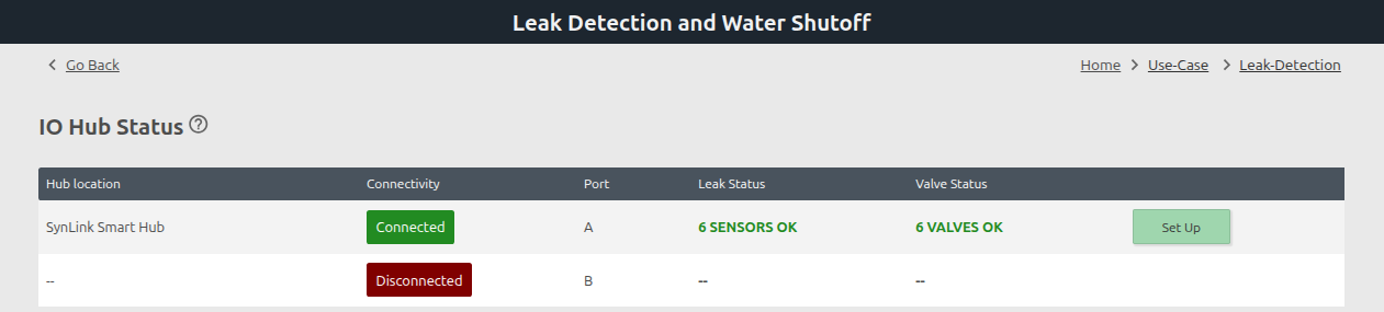
Figure 9 — First-time status: port A is connected, all valve outputs are on, and the hub is ready for Set Up.
Checkpoint: A new installation should resemble Figure 9: the intended port is Connected, Valve Status is normal, and the button says Set Up. If the button says Edit, leak automation already exists; review the existing configuration before changing it.
After automation is saved, this page may also appear under System > Leak Detection, and Set Up changes to Edit.
3. Enter alert recipients and delays
- Enter the actual person or distribution list responsible for the protected area under Where should alerts be sent? A second address is optional.
- Enable Alert when sensor is disconnected so loss of the hub connection is reported.
- Enable Alert when user switch is triggered so use of the hub's emergency Power Output switch is reported.
- Set Level 1 Trigger Delay. The example uses 5 seconds. After a sensor stays wet for this delay, the PDU sends the first email and shuts off every valve mapped to that sensor.
- Set Level 2 Trigger Delay. The example uses 120 seconds. If the leak remains present, the PDU sends the escalation email.
The accepted trigger range is 3–86400 seconds. Choose values based on spill rate, process risk, normal condensation, and the facility's response plan. Do not use a long delay merely to hide nuisance alarms; correct sensor placement or polarity instead.
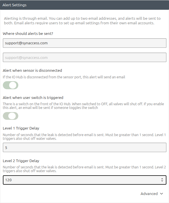
Figure 10 — Completed example: support recipient, both equipment alerts enabled, and 5/120-second delays.
Checkpoint: Before continuing, at least one real recipient must be present, both recommended alert toggles should be on, and both delay fields must contain the approved values.
4. Set the wet input state
- Expand Advanced.
- Set Digital IO State for leak detected to the wet state observed during the dry/wet test.
- For the supplied dry=LOW, wet=HIGH detector, select HIGH.

Figure 11 — HIGH selected as the wet state for the supplied leak detector.
Checkpoint: The switch should be toward HIGH, as shown in Figure 11, only if the physical wet test produced HIGH.
Do not leave this setting unverified. If a dry sensor reports LOW but the wizard is saved with LOW selected as “leak detected,” the PDU will interpret the dry condition as a leak and may immediately shut off mapped valves after the Level 1 delay.
5. Enable and label each connected leak sensor
- Under Leak Sensor Location, enable only channels with a physically connected and tested leak sensor.
- Enter a name that identifies the protected area. The example uses
Lab Bench Leak Ropeon Digital Input 1. - Verify that Leak Sensor 1 names the detector physically connected to Digital Input 1, and so on.
- Leave unused channels disabled. A disabled channel does not send email or shut off a valve.
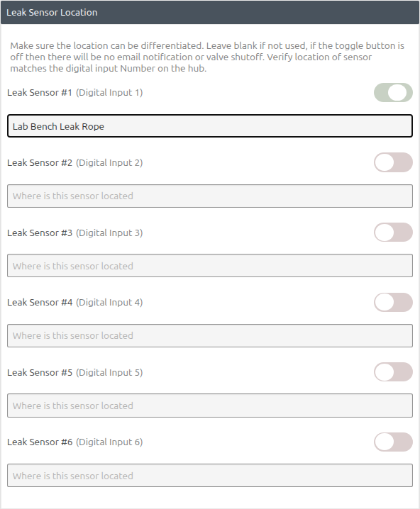
Figure 12 — Only the connected detector is enabled and labeled; unused inputs remain disabled.
Checkpoint: Every enabled row must correspond to a connected DT sensor lead, and its name must match the physical channel label. Unused rows should look like Sensors 2–6 in Figure 12.
6. Label each connected water valve
- Under Water Valve Location, enter a unique name for every connected valve.
- Verify that Water Valve 1 names the valve physically connected to Power Output/Output Relay 1, and so on.
- Leave unused valve channels blank and never select them in a mapping.
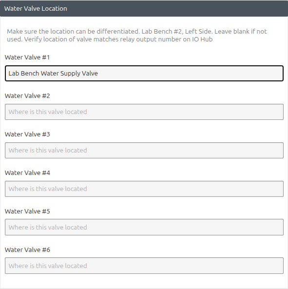
Figure 13 — Valve 1 is labeled Lab Bench Water Supply Valve; unused valve rows remain blank.
Checkpoint: Each entered valve name must match the numbered DT output lead and the physical pipe it controls.
7. Map sensors to shutoff valves
Under Leak Sensor to Shutoff Valve Mapping, select every valve that must close when that sensor detects water. One sensor can select multiple valves, and the same valve can be selected for multiple sensors.
Checkpoint: The selected valve tags must match the port plan. Each sensor row must contain every valve that should shut off for that sensor—and no other valves.
Review the three common patterns below before saving.
Figures 14B and 14C show alternate selections staged before Save. Email icons can remain gray while a changed mapping is unsaved. After Save finishes, verify the Level 1 and Level 2 email icons are green for every enabled sensor.
One sensor to one valve
Use when a leak zone has a dedicated supply.
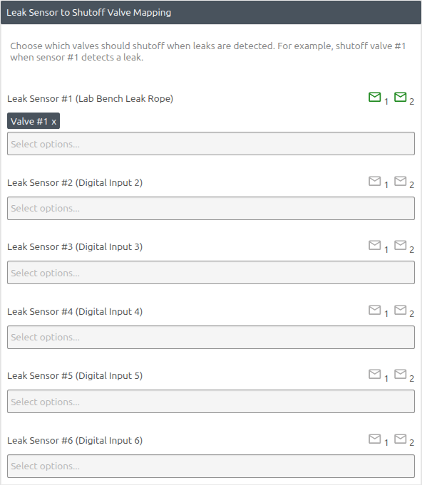
Figure 14A — One-to-one mapping: Sensor 1 shuts off Valve 1.
| Leak sensor | Select |
|---|---|
| Sensor 1 — Test Stand 1 | Valve 1 — Test Stand 1 Supply |
Result: only valve 1 shuts off when sensor 1 detects water.
One sensor to many valves
Use when one leak zone can receive water from several supplies or return paths.
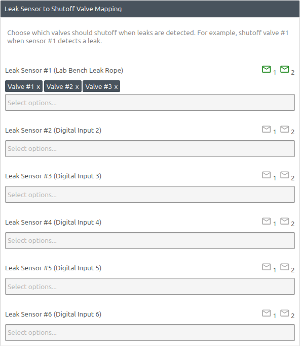
Figure 14B — One-to-many mapping: Sensor 1 shuts off Valves 1, 2, and 3.
| Leak sensor | Select |
|---|---|
| Sensor 1 — Shared Equipment Tray | Valve 1 — Cold Supply; Valve 2 — Hot Supply; Valve 3 — Return |
Result: valves 1, 2, and 3 shut off together when sensor 1 detects water.
Many sensors to one valve
Use when several leak zones share one upstream isolation valve.
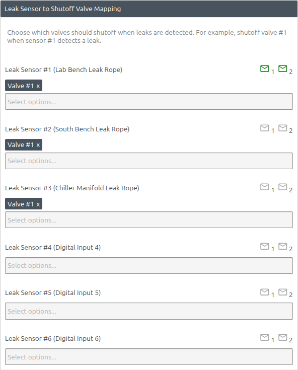
Figure 14C — Many-to-one mapping: Sensors 1, 2, and 3 each shut off Valve 1.
| Leak sensor | Select |
|---|---|
| Sensor 1 — North Bench | Valve 1 — Main Lab Supply |
| Sensor 2 — South Bench | Valve 1 — Main Lab Supply |
| Sensor 3 — Chiller Manifold | Valve 1 — Main Lab Supply |
Result: any one of sensors 1, 2, or 3 shuts off valve 1.
8. Review, save, and verify
Before selecting Save, verify:
- The correct hub port, A or B, is open.
- Every enabled sensor name matches its digital input number.
- Every valve name matches its output number.
- The selected wet state matches the physical dry/wet test.
- Every sensor maps only to valves that are wired and safe to close.
- Level 1 and Level 2 delays match the response plan.
- Recipient addresses are correct and SMTP has passed its test.
Select Save once. The wizard creates or updates several sensor names, actions, and event triggers. Keep the browser open while Saving... is displayed. Do not reload the page, power off the PDU, or disconnect the hub. Wait until the button returns to Save and the success details finish.
Return to Leak Detection and Water Shutoff and compare the result with Figure 15.
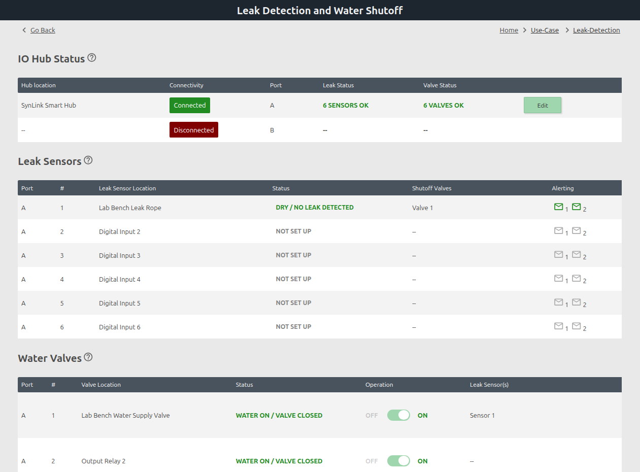
Figure 15 — Verified saved example: hub connected, sensor dry, Valve 1 mapped, both alert levels active, and all valves on.
Checkpoint: The hub button should now say Edit. Sensor 1 should show its location, DRY / NO LEAK DETECTED, Valve 1, and green Level 1/2 email icons. Valve 1 should show its location, Operation ON, and Sensor 1 in the Leak Sensor(s) column.
Firmware 2.5.118 displays WATER ON / VALVE CLOSED in the status column. For this screen, use WATER ON and Operation ON as the intended normal supply state, then verify the physical valve and water flow during commissioning.
The Reset Leak Detection Automation button removes the generated automation. It is not a normal troubleshooting or alarm-reset button. Use it only when you intentionally want to remove the configuration.
If a second hub is installed, return to IO Hub Status and repeat the wizard for the other port.
Part 5 — Commissioning test
Test one sensor and its complete mapping at a time. Have someone stationed at the valve and process equipment, and keep the manual upstream isolation accessible.
Test each sensor
- Confirm the rope is dry and the page reports DRY / NO LEAK DETECTED.
- Confirm every mapped valve is in the expected normal WATER ON state.
- Wet a short section of the rope with clean tap water.
- Confirm the input changes to the configured wet state.
- After the Level 1 delay, confirm all of the following:
- The page reports LEAK DETECTED.
- Every mapped valve changes to WATER OFF / VALVE CLOSED.
- Unmapped valves do not move.
- The Level 1 email arrives at every configured address.
- Logging > Event Log records the event and the valve/email actions.
- Keep the test area wet until the Level 2 delay and confirm the escalation email arrives.
- Remove the water, dry the rope completely, and confirm DRY / NO LEAK DETECTED returns.
- After verifying the area is safe, manually restore the valve through the GUI and confirm normal flow.
Repeat for every enabled sensor. For a one-to-many mapping, observe every mapped valve. For a many-to-one mapping, test each sensor independently and confirm each one closes the shared valve.
Test the emergency hub switch
- With the installation in a controlled test state, move the Smart Hub Power Output switch to OFF.
- Confirm all connected automatic-return valves lose power and close.
- Confirm the user-switch email alert is received, if enabled.
- Attempt no remote reopening while the switch is OFF. The hub keeps its output relays open and ignores requests to close them.
- Return the switch to ON only after the process is safe, then restore individual valves deliberately.
Test hub disconnect notification
Perform this test only during an approved maintenance window.
- Create a safe process state and close or isolate water as required.
- Disconnect the hub interface cable from the PDU sensor port.
- Confirm the hub shows Disconnected and the configured email arrives.
- Reconnect the cable and confirm the hub and all channels return.
Normal operation and leak response
When a real leak occurs:
- Treat the email as a prompt to inspect, not as proof that every valve closed successfully.
- Check the PDU Leak Detection page to identify the wet sensor, mapped valve actions, and event log.
- Use the hub's front Power Output OFF switch or the facility's manual isolation if a broader emergency shutoff is needed.
- Find and repair the leak source.
- Clean and completely dry the sensing rope. Replace it if damaged or contaminated.
- Confirm the GUI reports DRY / NO LEAK DETECTED.
- Have an authorized person inspect the affected equipment and plumbing.
- Move the hub switch to ON, if it was turned off, and manually restore only the required valve or valves.
- Watch the repaired area during a controlled return to service and document the incident.
The automation intentionally does not reopen water merely because the sensor becomes dry. This prevents an intermittent leak, moved rope, power disturbance, or accidental drying from restoring flow without inspection.
Troubleshooting
| Problem | Checks and corrective actions |
|---|---|
| Smart Hub does not appear | Confirm hub input power and status LEDs; confirm the interface cable runs from the hub SynLink Interface to PDU Sensor A or B; do not use a LAN port; refresh System > Sensors. |
| All valves remain off | Check whether the hub's front Power Output/User Switch is OFF. While OFF, the hub keeps relays open and ignores remote ON requests. Turn it ON only after confirming the process is safe. |
| Dry rope reports a leak | Dry and clean the rope; verify the physical digital input number; repeat the dry/wet state test; correct the Advanced HIGH/LOW selection. |
| Wet rope does not trigger | Confirm the channel is enabled, the wet state changes at System > Sensors, the Advanced polarity matches, the Level 1 delay has elapsed, and the automation Save completed. |
| Wrong valve closes | Compare sensor and valve cable labels with hub channel numbers; correct the mapping; repeat the controlled test for every sensor. |
| Valve does not close | Verify the selected mapping and output number; inspect the DT connector and actuator power; use a safe manual operation test; have a qualified installer check valve sizing, direction, obstruction, and pressure. |
| Valve cannot be reopened remotely | Confirm the rope is dry, the hub front switch is ON, and the correct output is selected. Inspect event logs and the physical valve before retrying. |
| No email arrives | Confirm the PDU can reach DNS/network services; verify SMTP host, port, TLS, authentication, and recipient; run Send Test Email; check mail-gateway and spam logs. Valve automation must still be tested locally. |
| Second hub mappings are missing | Return to IO Hub Status and select the other port. The wizard configures each hub independently and does not offer cross-hub mappings. |
| Save does not finish cleanly | Do not press Reset. Review the on-screen save details, reload the status page, and verify the expected sensor names, mappings, actions, and events before attempting another change. |
Installation record
Record the final configuration and keep it with the facility's maintenance documentation.
- PDU model and serial number:
- PDU firmware version:
- PDU network name/IP:
- Hub A serial/asset ID and location:
- Hub B serial/asset ID and location:
- Level 1 delay:
- Level 2 delay:
- Alert recipients:
- SMTP test date/result:
- Sensor/valve mapping worksheet attached: Yes / No
- Wet test date and technician:
- Emergency switch test result:
- Hub disconnect test result:
- Next scheduled inspection/test:
Reference and validation basis
- GUI steps and screenshots were captured while creating the Figure 10–15 example live on a SynLink SP PDU running controller firmware 2.5.118 on August 14, 2026. The example configuration was saved and verified through the device APIs.
- Live changes were limited to sensor/valve labels and leak automation configuration. No valve was switched, no leak was triggered, and no external SMTP test message was sent during documentation capture.
- SPA-0150 hardware identification and DT connector instructions are based on the supplied SPA-0150 product photographs.
- Relay/valve terminology and automation behavior were checked against the firmware 2.5.118 GUI and the corresponding local firmware/frontend implementation.
- Menu names can vary slightly with firmware version and account permissions. Contact Synaccess Support when the connected hub, automation use case, or required permissions are not visible.