
Use this guide to connect one leak rope to one water valve and create automatic shutoff and email alerts. Repeat the same steps for additional sensors and valves.
Have a qualified plumber install the valve and keep a manual water shutoff available. Do not restore water after an alarm until the leak has been repaired and the area inspected.
What you need
- SynLink SP PDU connected to your network
- SPA-0150 Smart Hub, power supply, and PDU interface cable
- Leak-detector module and rope sensor
- Compatible automatic-return water valve
- SMTP email settings and an alert recipient
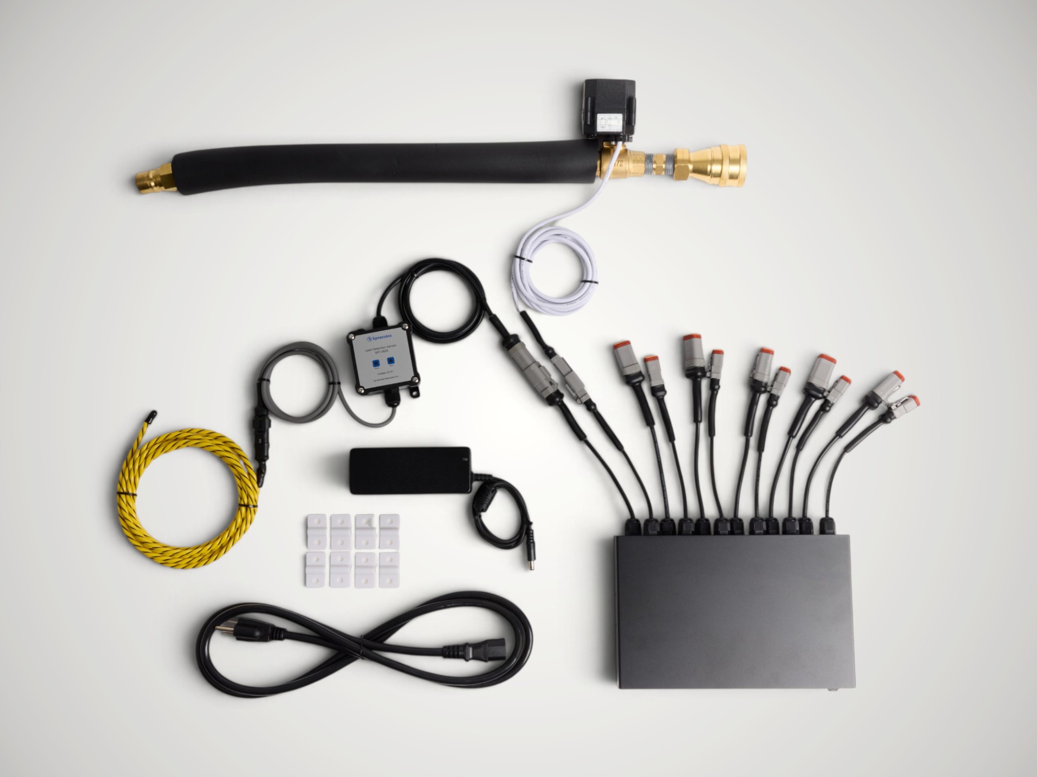
1. Connect the hardware
- Have a qualified plumber install the automatic valve with the water isolated and depressurized.
- Place the leak rope beneath the equipment or pipework you want to protect. Keep the detector module and connectors dry.
- Set the SPA-0150 Power Output switch to OFF.
- Connect the leak detector to Sensor/Digital Input 1 using its DT connector.
- Connect the water valve to Power Output/Output Relay 1 using its DT connector.
- Connect the SPA-0150 power supply.
- Connect the hub SynLink Interface to PDU Sensor Port A or B.
- Turn the hub Power Output switch ON when the plumbing is ready.
2. Confirm email works
- Log in to the PDU web page.
- Open Settings > SMTP.
- Enter the SMTP server, port, TLS, username, and password supplied by your email administrator.
- Select Save, then use Send Test Email.
- Continue only after the test message arrives.
3. Open Leak Detection setup
- Open Automation > Use Cases.
- Select Leak Detection and Water Shutoff for Smart IO Hub Accessory.
- Find the connected hub and select Set Up.
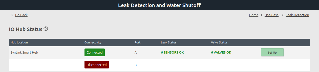
Your hub should show Connected, normal valve status, and Set Up.
4. Enter alert settings
- Enter the email address or distribution list that should receive leak alerts.
- Enable the sensor-disconnected and user-switch alerts.
- Set Level 1 to 5 seconds and Level 2 to 120 seconds, unless your site requires different delays.
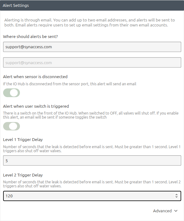
- Before saving, check the input with the rope dry, wet a short section with clean water, and check it again. The two states must be different. Dry the rope completely after the test.
- Expand Advanced and select the state you observed while the rope was wet. The supplied detector is normally dry=LOW and wet=HIGH, so select HIGH when that is what your test shows.

Selecting the wrong wet state can shut off water while the rope is dry. Verify this setting before saving.
5. Name and map the equipment
- Enable Leak Sensor 1 and name it for its location, such as
Lab Bench Leak Rope. Leave unused sensor rows disabled. - Name Water Valve 1, such as
Lab Bench Water Supply Valve. Leave unused valve rows blank. - Under Leak Sensor to Shutoff Valve Mapping, select Valve #1 for Leak Sensor 1.
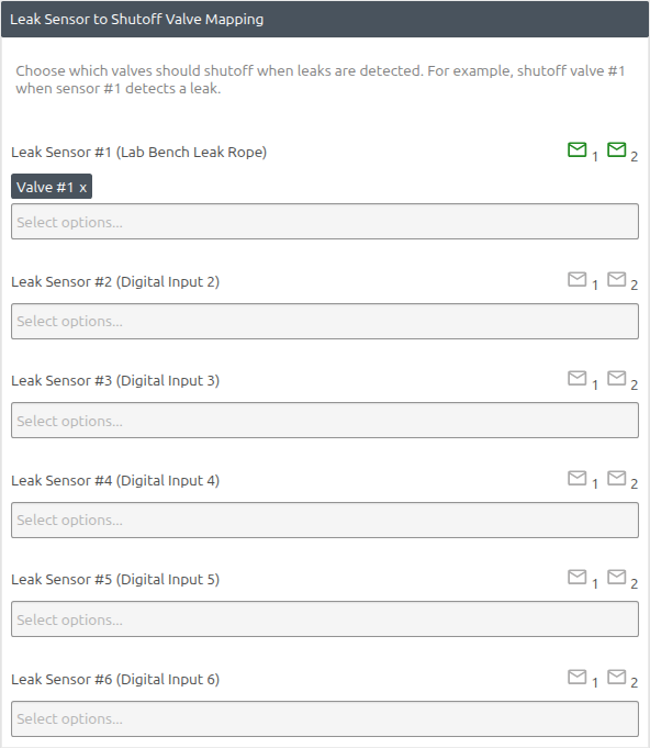
This mapping means water detected by Sensor 1 shuts off Valve 1.
6. Other mapping options
Use these patterns when one sensor and one valve are not enough.
The alternate screenshots below show selections before Save. Email icons can remain gray while a changed mapping is unsaved; verify they turn green for each enabled sensor after Save finishes.
One sensor to many valves
Use this when one leak area can receive water from several lines. In the row for Leak Sensor 1, select every valve that must shut off.
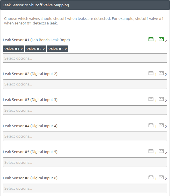
In the setup page, the Sensor 1 mapping should show Valve #1, Valve #2, and Valve #3. A leak detected by Sensor 1 shuts off all three valves.
Many sensors to one valve
Use this when several leak areas share one main supply valve. Select the same valve in each sensor row.
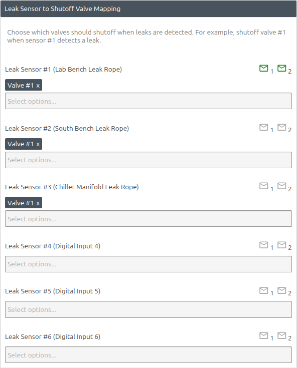
In the setup page, the rows for Sensors 1, 2, and 3 should each show Valve #1. A leak detected by any one of these sensors shuts off Valve 1.
Only map a sensor to valves on the same SPA-0150. Before saving, compare every selection with the physical sensor and valve labels.
7. Save and check the result
- Select Save once.
- Keep the page open while Saving... is displayed.
- Return to the Leak Detection page after Save finishes.
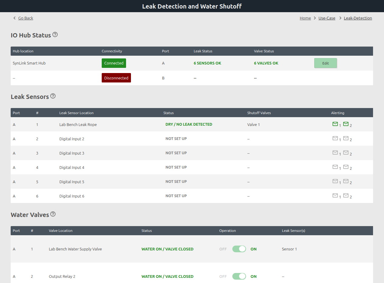
Confirm:
- The hub button says Edit.
- Sensor 1 shows its name and DRY / NO LEAK DETECTED.
- Sensor 1 lists
Valve 1and has green Level 1/2 email icons. - Valve 1 shows its name, Operation ON, and
Sensor 1.
Firmware 2.5.118 may display WATER ON / VALVE CLOSED. Use WATER ON and Operation ON as the intended normal state, then verify the physical valve and water flow.
8. Perform a controlled test
- Make sure someone is present at the valve and the manual water shutoff is accessible.
- Wet a short section of rope with clean water.
- After the Level 1 delay, confirm Valve 1 closes and the first email arrives.
- Keep the rope wet until the Level 2 email arrives.
- Dry the rope completely and confirm DRY / NO LEAK DETECTED.
- Inspect the area, then manually restore the valve and confirm normal flow.
The system does not reopen water automatically after the rope dries.
For two hubs, detailed commissioning, and troubleshooting, use the complete setup guide.